Embedded systems & robotics2026
Pico 2 Robot with PID Speed Control
A two-wheel robot on a Raspberry Pi Pico 2, written in C, that holds each wheel's speed with encoder feedback and PID, and drove a straight 6 second run with its wheels 2 pulses apart.
Select any part of the robot to see what it does.
A test run, animated in your browser. The pulse counts are from the lab report; the speed curves are drawn to show how the loop behaves, not recorded.
- Role
- Firmware, wiring and testing
- Timeline
- Fall 2026, CSE325 at ASU
- Team
- Solo or team size
- Stack
- C,
- Raspberry Pi Pico SDK 2.3.1,
- RP2350 (Arm Cortex-M33),
- PWM and GPIO interrupts,
- CMake,
- VS Code
- Links
Overview
A two-wheel robot for CSE325 at ASU, built on a Raspberry Pi Pico 2 with two DC motors on a dual H-bridge, and grown in phases. In Phase 1, each flip of a switch makes the robot drive one smooth circle to the left or right, while the firmware prints the chip's GPIO registers to the serial monitor. In Phase 2, wheel encoders and a PID loop per motor hold the robot's speed, so it drives straight for 6 seconds. More phases are still to come.
Problem
The two motors are not equal. At the same 65% PWM with the wheels off the ground, the left wheel counted 339 and 340 pulses in 2 seconds and the right counted 398 both times. On the floor, a run without any correction curved sharply left, with the right wheel 210 pulses ahead (714 against 924).
Approach
Each wheel has a quadrature encoder whose A channel fires a rising-edge interrupt that adds to a counter, so pulses are counted while the main program checks the switch and adjusts PWM. Every 100 ms each motor runs its own PID loop against a target of 12 pulses per 100 ms, with its PWM kept between 40% and 80%. On top of that, a sync check every 5 ms cuts the right motor's forward drive for a moment whenever it is more than 2 pulses ahead.
Phases
Phase 1Done
Switch-driven circles
Each flip of an SPDT switch, debounced, makes the robot drive one smooth circle to that side, one wheel at 70% duty and the other at 40%, then stop and wait. The firmware prints the SIO GPIO_IN, GPIO_OUT and GPIO_OE registers before and during each move.
Phase 2In progress
Holding speed with encoders and PID
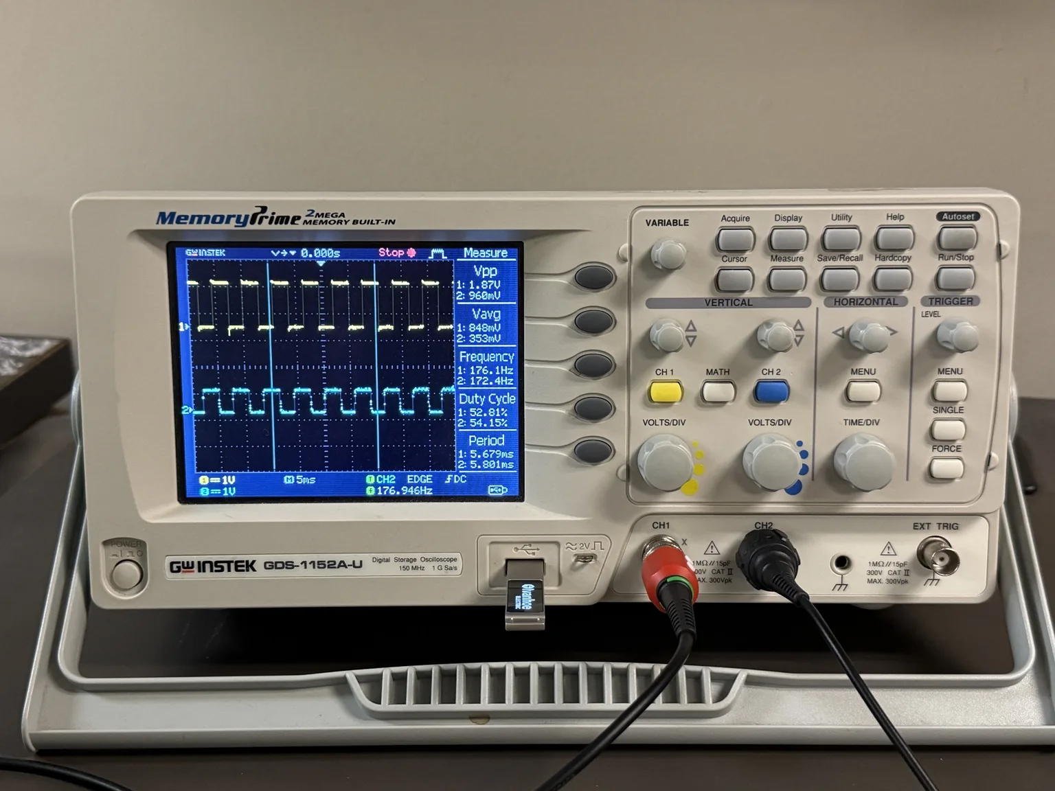
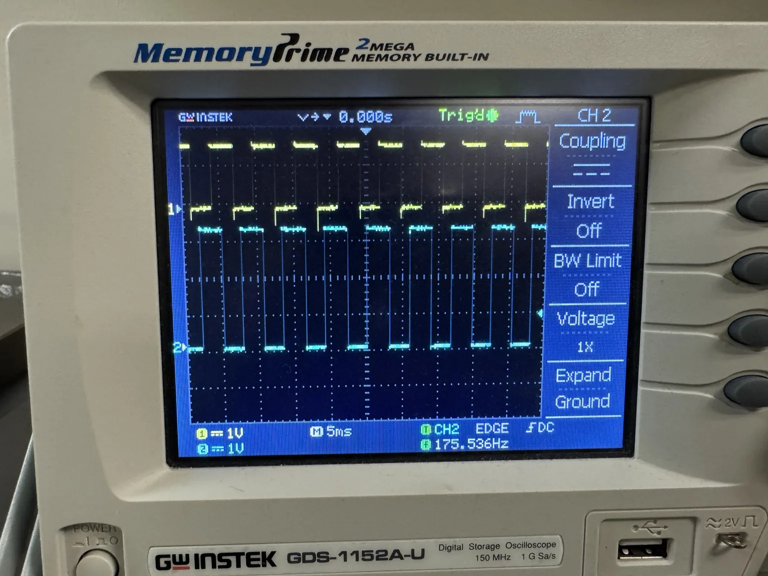
Wheel encoders counted in interrupts, a PID loop per motor and a 5 ms sync check. The floor run drives straight with the wheels 2 pulses apart, and both encoder signals were checked on an oscilloscope. Still to do: the same run on a second surface, with the two travel distances within 5% of each other, and a video of both.
Phase 3Upcoming
Phase 3 title
What the next phase adds to the robot
How the robot drives
One run
Everything a run does, from the switch to the stop. Counting happens in interrupts, so it never waits on the rest.
- check
- tool
- person
01 / 05person
Switch on
Flipping the switch, debounced at 300 ms, starts the run. The robot waits 2 seconds, then drives.
02 / 05tool
Count pulses
A rising edge on each encoder's A channel fires an interrupt that adds to a volatile counter for that wheel.
03 / 05tool
PID every 100 ms
Each motor compares its pulses in the last 100 ms with the target of 12 and sets its own PWM from the error, its sum and its change, kept between 40% and 80%.
04 / 05check
Sync every 5 ms
If the right wheel's total is more than 2 pulses ahead of the left, its forward drive is cut for a moment so the left can catch up.
05 / 05tool
Stop after 6 s
Both motors stop, and the serial monitor shows the counts and PWM for the run.
Finding why it curved
The robot kept curving left. Each test ruled something out before the fix.
- check
- tool
01 / 04check
One motor at a time
Running the motors one at a time confirmed the encoder assignments were right.
02 / 04check
Same PWM, wheels up
At 65% PWM with the wheels off the ground, the left wheel counted 339 and 340 pulses in 2 seconds, the right 398 both times: the motors themselves differ.
03 / 04tool
Tuning alone
Changing the target speed, the PID gains and the starting PWM, and lowering the right motor's PWM, still left a large curve to the left.
04 / 04check
Add the sync check
A second check on the encoder totals, alongside the PID loops, brought the gap from 210 pulses to 2, and the robot drove straight.
Architecture
- Switch to Main loop
- Encoders to Interrupts, edges
- Interrupts to PID loops, counts
- Main loop to PID loops
- Interrupts to Sync check
- PID loops to PWM, duty
- Sync check to Direction pins
- PWM to H-bridge
- Direction pins to H-bridge
- H-bridge to Motors
Gallery
Challenges and solutions
- Challenge: The right motor was always faster.
- Solution: Lowering its PWM alone did not fix the curve. The final version pairs a PID loop per motor with a second check on the encoder totals that briefly holds back the right wheel when it gets more than 2 pulses ahead.
- Challenge: Counting every pulse while the program does other work.
- Solution: Encoder pulses are counted in rising-edge interrupts into volatile counters, so counting carries on while the main program checks the switch and adjusts PWM.
- Challenge: Seeing what the hardware is actually doing.
- Solution: Phase 1 prints the SIO GPIO_IN, GPIO_OUT and GPIO_OE registers before and during each move. Phase 2 prints counts and PWM over USB serial, which is how the late dip in both motors' pulses showed up, and an oscilloscope on both encoder channels confirmed clean square waves.
Outcomes
- Final run: 635 pulses left and 637 right, a gap of 2 (0.31%), down from 210 without the sync check, and the robot drove straight for the full 6 seconds.
- Encoder signals checked on an oscilloscope: square waves at 176.1 Hz left and 172.4 Hz right with the wheels raised.
- Switch-driven circles in Phase 1: one wheel at 70% duty and the other at 40% for 5 seconds.